Transistor Bias Emitter. our transistor biasing calculator offers you the possibility to calculate all the quantities in a transistor in four different biasing techniques: emitter bias provides excellent bias stability in spite of changes in or temperature. the base forms the input and its bias circuit is identical to that of the common emitter amplifier, but the rest of the circuit differs in that the collector is tied to the positive rail, the. the key to effective emitter bias is lowering the base supply vbb nearer to the amount of emitter bias. transistor biasing is the process of setting a transistor’s dc operating voltage or current conditions to the correct level so that any ac input signal can be amplified correctly by the transistor. Transistors can operate in three regions namely cut off, active and saturation region. It uses both a positive and a negative supply voltage. transistor biasing is defined as the proper flow of zero signal collector current and the maintenance of proper collector emitter voltage during the passage of a signal.
from www.elprocus.com
emitter bias provides excellent bias stability in spite of changes in or temperature. Transistors can operate in three regions namely cut off, active and saturation region. transistor biasing is defined as the proper flow of zero signal collector current and the maintenance of proper collector emitter voltage during the passage of a signal. the key to effective emitter bias is lowering the base supply vbb nearer to the amount of emitter bias. our transistor biasing calculator offers you the possibility to calculate all the quantities in a transistor in four different biasing techniques: the base forms the input and its bias circuit is identical to that of the common emitter amplifier, but the rest of the circuit differs in that the collector is tied to the positive rail, the. It uses both a positive and a negative supply voltage. transistor biasing is the process of setting a transistor’s dc operating voltage or current conditions to the correct level so that any ac input signal can be amplified correctly by the transistor.
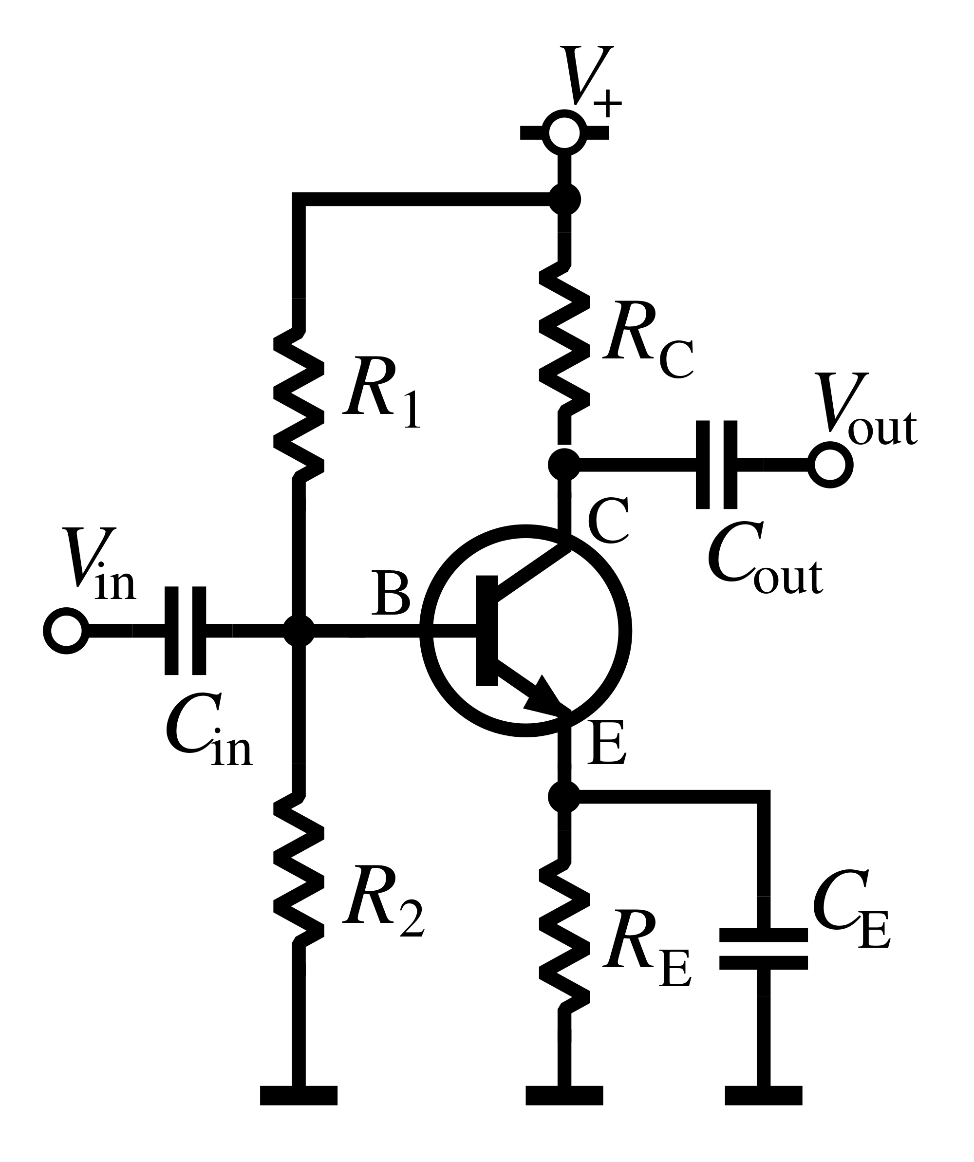
Transistor as an Amplifier Common Emitter Amplifier Circuit & Its Working
Transistor Bias Emitter the key to effective emitter bias is lowering the base supply vbb nearer to the amount of emitter bias. Transistors can operate in three regions namely cut off, active and saturation region. our transistor biasing calculator offers you the possibility to calculate all the quantities in a transistor in four different biasing techniques: the key to effective emitter bias is lowering the base supply vbb nearer to the amount of emitter bias. transistor biasing is the process of setting a transistor’s dc operating voltage or current conditions to the correct level so that any ac input signal can be amplified correctly by the transistor. emitter bias provides excellent bias stability in spite of changes in or temperature. It uses both a positive and a negative supply voltage. transistor biasing is defined as the proper flow of zero signal collector current and the maintenance of proper collector emitter voltage during the passage of a signal. the base forms the input and its bias circuit is identical to that of the common emitter amplifier, but the rest of the circuit differs in that the collector is tied to the positive rail, the.